
Building Pulpwood Cars
Richard Day
April 2010
In East Texas where I grew up, the harvesting and shipping of pulp wood was a common sight. Trucks delivered the cut logs to shipping yards where the logs were placed on rail cars designed for that purpose. Pulpwood cars were very similar to today’s bulk head flats with the major difference being the floors of the cars were sloped toward the center sill and in many cases the bulkheads were open frames. I recently decided to try and build a 50’s era pulpwood car in 1.5” scale. Photo 1 below shows a completed car.
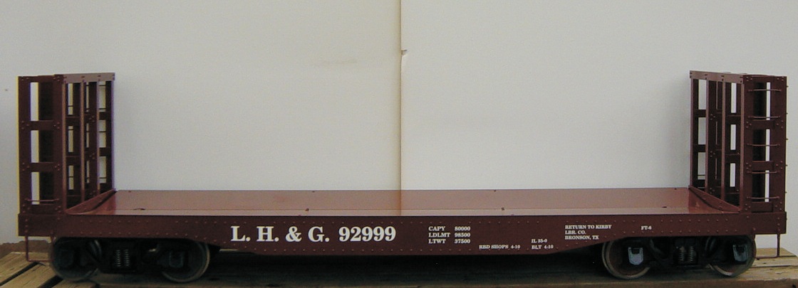 Photo 1
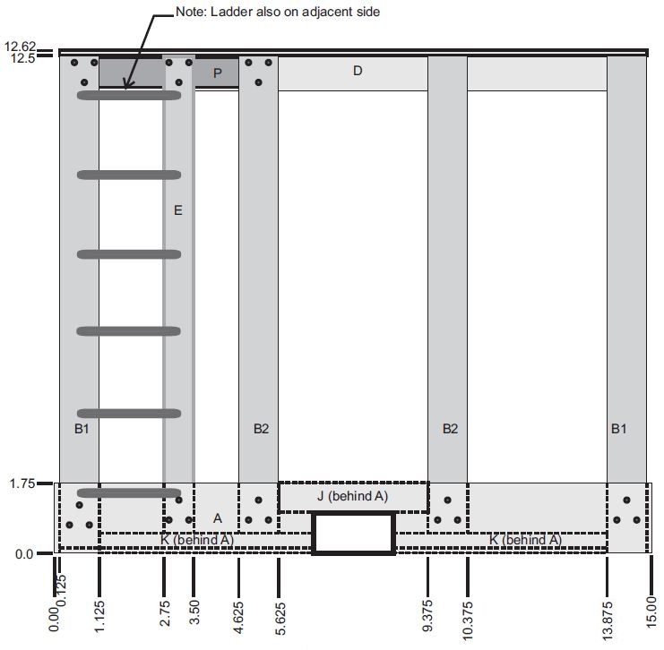 Figure A. End View
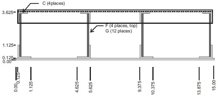 Figure B. Top View
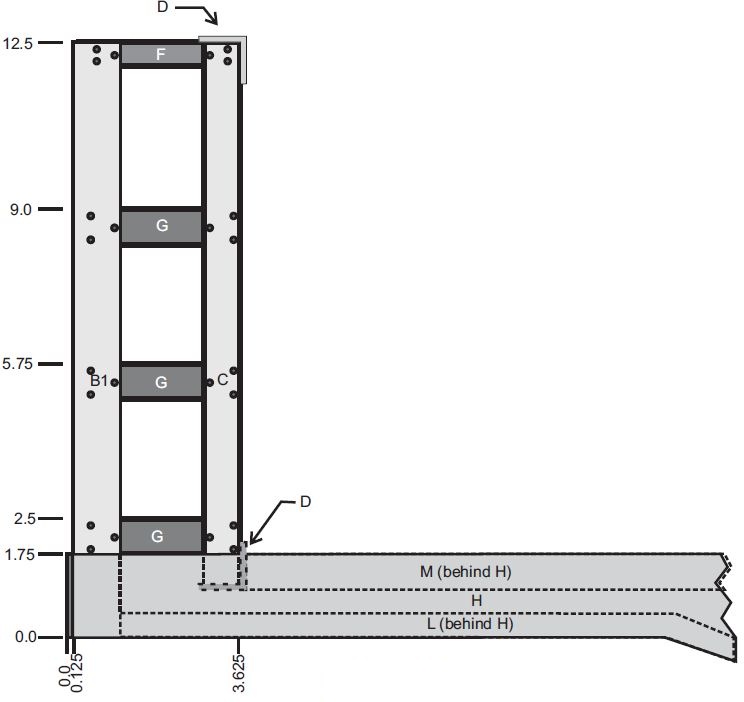 Figure C. Side View
The construction of my car began by creating a drawing of the bulkhead ends. To me, that was the most difficult part of building the car. The sides of the car do not present a significant challenge as they are basically that of a 40’ flat car without stake pockets. My goal was to use easily obtainable shapes for the bulkheads, so some deviation to actual dimensions was necessary. An HO model as well as car drawings found on the web were used to determine the key dimensions. I made end view, top view, and side view drawings of the bulkheads. These are shown in Figures A, B, and C. Admittedly, the drawings are simple, but they provided the details needed to construct the car.
With the drawing in hand I decided it would be good to build a mock up before purchasing the aluminum materials needed. Scrap pieces of 1/4” plywood were used for the mock up. These were nailed and glued together to form the angle pieces needed. Admittedly, the 1/4” thickness of the plywood material makes everything look very chunky, but it did help verify the concept and the dimensions. Photos 2 and 3 show my plywood mock up of the bulkhead. I only modeled the outside bulkhead frames as this was all that was needed to verify the design.
At this point I was ready to select and order the materials needed for the bulkheads and sides. These materials are architectural aluminum angles, bar stock, and plate. The bill of materials lists the type and quantity of angle and bar stock needed. The plate needed for the side and end sills is not listed but I would recommend 1/8” thick material.
 Photo 2. Mock Up Side View
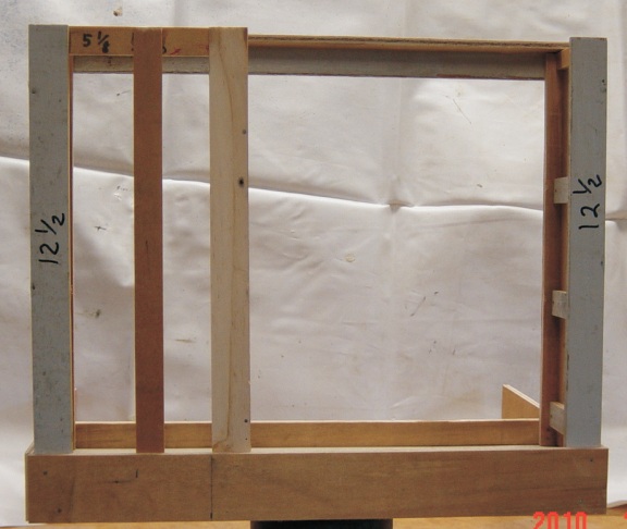 Photo 3. Mock Up End View
Each part in the material list is identified by an alpha character. These same characters are shown on the drawings to identify the parts. I used 3/32” rivets to assemble the pieces except is situations where it was too difficult to install rivets. In these locations I used 4-40 button head screws. If it was convenient to use nuts on the screws I did and where it was not I drilled and tapped the holes for the 4-40 screws. Rivets and or screws were installed in triangular patterns where parts were joined together. I modified the spacing of the rivets in the triangular patterns as needed to fit the various sizes of material.
| Part | Qty | Description |
| A | 2 | 1 3/4 X 15.0 X 1/8 Al Plate (end sill) |
| H | 2 | 3 x 60 x 1/8 Al Plate (side sill) |
| B1 | 4 | 1 x 1/8 Al angle, 12 1/2″ long |
| B2 | 4 | 1 x 1/8 Al angle, 12″ long |
| D | 4 | 1 x 1/8 Al angle 14 3/4″ long |
| C | 8 | 3/4 x 1/8 Al angle 11 3/8″ long |
| J | 2 | 3/4 x 1/8 al angle 3 3/4″ long |
| M | 2 | 3/4 x 1/8 Al angle 60″ long, upper side sill |
| F | 8 | 1/2 x 3 1/4 x 1/8 Al Bar |
| E | 2 | 3/4 x 12 1/2 x 1/8 Al Bar |
| G | 24 | 3/4 x 3 1/4 x 1/8 al Bar |
| K | 2 | 1/2 x 1/8 Al angle 5 3/8″ long |
| L | 2 | 1/2 x 1/8 Al angle 60″ long, lower side sill |
| P | 1 | 3/4 x 5 1/8 x 1/8 Al Bar |
I began construction of the bulkheads by sawing up the aluminum angles and bars into the pieces needed for each end. The sawing was done on my radial arm saw using a carbide tooth blade, but other cutting methods could be used. Once all the pieces were cut I marked the rivet patterns and used a number 39 bit to drill the appropriate rivet holes. Photo 4 shows a complete set of parts needed to build the bulkhead for one end of the car. The rivet hole patterns can be seen on the parts that have been drilled. Parts shown without rivet holes will be “line drilled” during the assembly of the bulkheads.
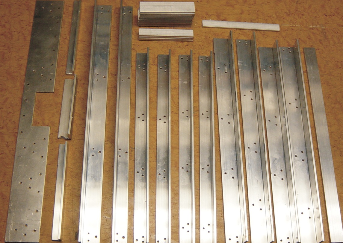 Photo 4. Parts for Bulkhead
The first pieces assembled were the end sills. Both sides of a completed end sill are shown in photo 5. The 1/2″ and 3/4″ angles were clamped to the end sill and drilled to match. The 3/32” rivets were then installed to complete this part of the assembly.
Four similar vertical frames are used to build each bulkhead end assembly. To set the parts up for drilling and assembly I made a holding fixture using a short piece of 2×4 lumber. First I marked the spacing for the 3/4″ and 1/2″ wide cross bars that connect the two angle pieces. Once marked I again used the saw to cut notches into the lumber so that the cross bars could be held in place. Next the 2×4 was cut to the width needed so that when the aluminum angles were clamped against the lumber, the short cross bar pieces are held in place. This fixture with the parts clamped in place is shown in Photo 6. The next step was to place the fixture on the drill press table and line drill through the angles to the cross bars. Once drilled, rivets were installed to complete each vertical frame assembly.
Photo 7 is a view of four completed frame assemblies that are used to build the bulkhead assembly. Close examination shows that the 1” angle on two frames in the photo is longer. These two frames are used as the outside frames of the bulkhead and will also serve to connect the car side sill to the end sill. The two frames with the shorter legs are the interior frames of the bulkhead. A completed bulkhead assembly is shown in Photo 8. Assembling the bulkhead was accomplished by first attaching the frame assemblies to part A (End Sill). Next, the upper and lower angle pieces part D were attached to the frame assemblies, followed by parts E and P (ladder supports). To complete the bulkhead assembly, grab irons to form the ladders were added. I made the grab irons using steel wire, but they can also be purchased from several suppliers.
With the bulkhead assemblies complete it was now time to attach them to the car side sills. The side sills are simple and are typical of that found on a flat car. Parts H, M, and L make up the side sills. Photo 9 is an inside view of one end of a side sill. The two support angles (parts M and L) are clearly visible. Photo 10 is an outside view of the same side sill. The four open holes on the end are used to attach the side sill to the bulkhead assembly.
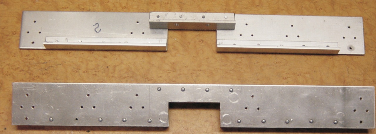 Photo 5. End Sill
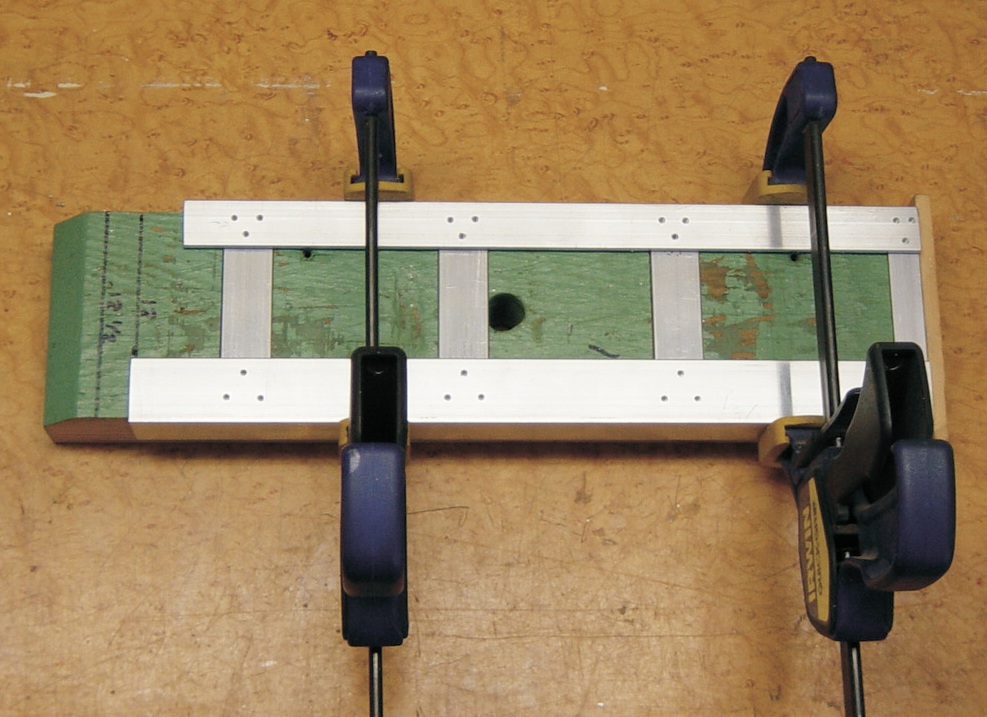 Photo 6. Bulkhead Frame Drill Fixture
The assembly of the side sills to the bulkheads began by clamping the side sills to the bulkhead assemblies and then line drilling through the side sills into the bulkhead assembly. Rivets could be used in the four holes to make the connection, but I chose to use 4-40 button head screws and nuts. This allowed me to test fit the parts and complete the car assembly prior to priming and painting. Once I was satisfied that everything fit properly, I disassembled the side sills from the bulkhead assemblies to prepare them for painting.
For my car I used 1” by 2” rectangular steel tube for the center sill and body bolsters. The rectangular cut out in the end sills provides a place to attach the center sill to the bulkhead ends. The ends of this tube also provide a place to mount couplers. With the side sills assembled to the bulkhead ends, the completed car body fits onto the 1” by 2” steel tube center sill . Angle pieces D and J of the bulkhead assemblies rest on the center sill. The car body was attached to the center sill by drilling through parts D, J and the center sill and installing 1/4” bolts. Since the construction of the center sill and body bolsters will vary depending on the type and manufacturer of the trucks used, I did not list the materials needed or provide a photo.
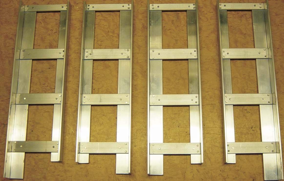 Photo 7. Frame Assemblies
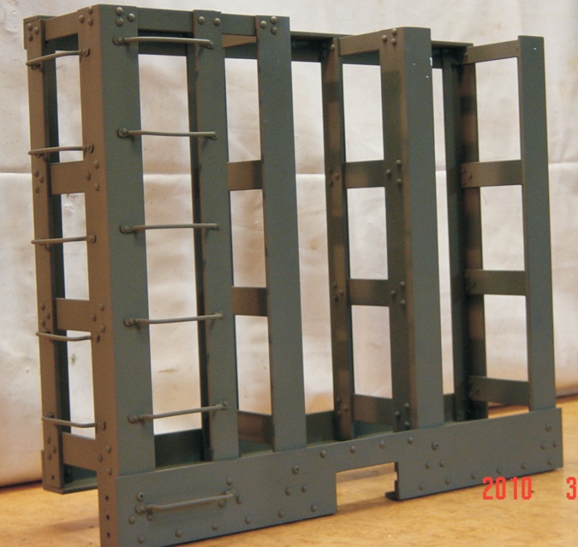 Photo 8. Completed Bulkhead Assembly
I have seen pulpwood cars with wood decks and with steel decks so either material would be appropriate. Since the deck slopes from the side sill to the center sill two deck pieces are required. For the deck of this car I used two 16 gauge steel plates. After the car body was assembled to the center sill I took measurements for the two deck pieces and had the steel plate cut. The deck plates are bolted to the side sill angle (part M) and to the center sill using 4-40 button head screws. This allows the deck to be sloped to the center of the car as was the case in most pulpwood cars.
Once I was satisfied that everything fit properly, I disassembled the car to make painting easier. All parts were first washed with soap and water. The aluminum parts were then coated with a self etching primer and the steel parts with a rusty metal primer. The self etching primer is key to helping insure the finish coat of paint bonds to the aluminum. The final finish used a good quality oil base enamel. Lettering for the car is adhesive backed vinyl decals that I had made locally at a sign shop.
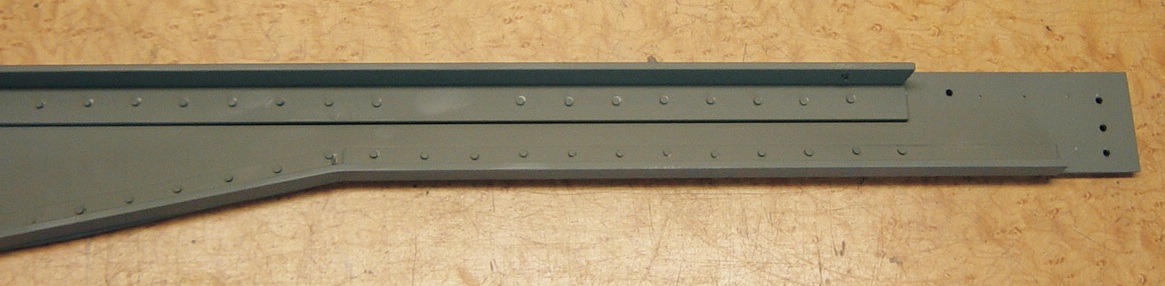 Photo 9. Side Sill (inside view)
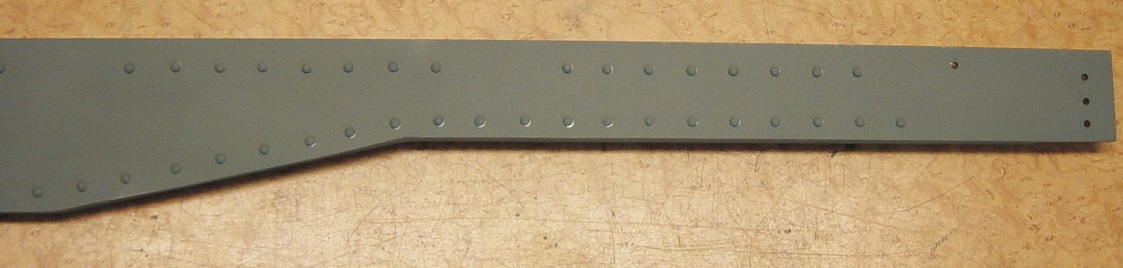 Photo 10. Side Sill (Outside View)
Below are a few more pictures of the completed cars as they begin to enter service. Finally, I must express my thanks to Jack Haskins and Bill Childers for their help with this project.
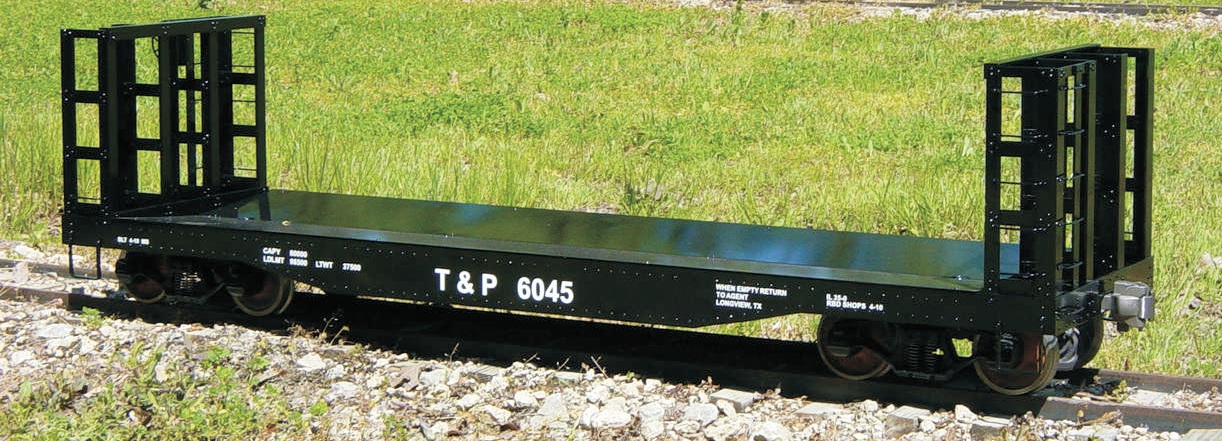 Photo 11
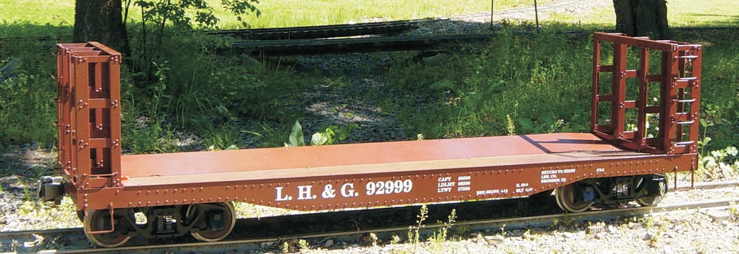 Photo 12